Lekce 1: Pelton Turbine
Kapitola 1: Pelton Turbine
Pelton turbine, also called Pelton wheel, is a water turbine, invented by American engineer Lester Allan Pelton in the 1870’s. It is a modified version of a turbine developed by Samuel Knight some time earlier. It is considered to be one of the most efficient types of water turbines.
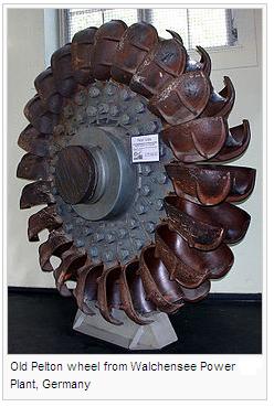
Description
The Pelton turbine is an impulse machine, which means that it acquires energy from a jet of water. The water goes through nozzles (up to 6), which direct it onto spoon-shaped buckets on the periphery of a runner. Thanks to this the runner rotates and produces mechanical energy, which is transmitted by the shaft to a generator. Because the momentum of the water has been transferred to the turbine, the water is decelerated and slowly flows out the other side of the buckets.
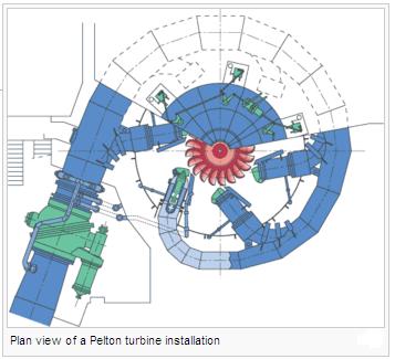
Application
Pelton turbines are most efficient at high heads (usually up to 1,800 meters, but higher are also possible), which allow them to get a lot of power from a water source with high pressure and low flows. They are produced in various sizes – some of them, used in hydroelectric plants, weigh many tons and their output is up to 200 megawatts. The smallest of them have a diameter of several centimetres and are used to extract power from mountain streams with flows about a dozen of litres per minute.
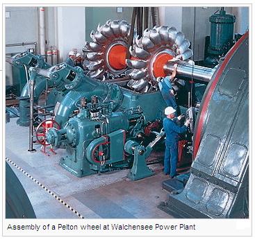
Vocabulary
Pelton turbine, Pelton wheel – Peltonova turbína
invented – vynalezený
efficient – výkonný
jet – prudký proud
nozzle – tryska
spoon-shaped bucket – lopatka ve tvaru lžíce
runner – lopatkové kolo
transmit, transfer – přenést
shaft – hřídel
momentum – pohybová energie
decelerate – zpomalit
application – využití
head – hydraulický spád
flow – proud
hydroelectric plant – vodní elektrárna
weigh – vážit
output – výkon
diameter – průměr
dozen – tucet
litre per minute – litr za minutu
Obrázky a fotografie použité v této kapitole pochází ze stránek {Wikimedia Commons XH http://commons.wikimedia.org}, kde byly zveřejněny pod licencí {GNU FDL XH http://commons.wikimedia.org/wiki/Commons:GNU_Free_Documentation_License}.
Kapitola 2: Cvičení
- Studenti zpracují na téma Pelton Turbine powerpointovou prezentaci.
Kapitola 3: Kontrolní otázky
- Can you briefly describe a Pelton turbine?
- How does it operate?
- Can you give some examples of its application?
Kapitola 4: Autotest
- How efficient are Pelton turbines?
- What shape are the buckets of the runner?
- What happens with the speed of the water in the turbine?
- Where are Pelton turbines most efficient?
- What is the output of some Pelton turbines used in hydroelectric plants?
Lekce 2: Francis Turbine
Kapitola 1: Francis Turbine
The Francis turbine is a form of a water turbine. It was invented by an American engineer James Francis. Nowadays they are the most common turbines.
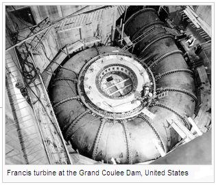
History
In the past people used water wheels to get the power from water, but they were not very efficient. First inventions of water turbines came in the first half of the 19th century. In 1826 French engineer Benoit Fourneyron invented an outward-flow turbine with the efficiency of 80 per cent. Another French engineer Jean-Victor Poncelet proposed an inward-flow turbine in that time, but it was not built until 1838. James Francis used his mathematical abilities to improve these designs and in 1848 built a turbine with the efficiency of 90 per cent.
Description
The Francis turbine is a radial reaction turbine. When the water goes through the turbine, it changes pressure and thus its energy is transmitted. That is why these turbines are usually located at the base of a dam, with the high pressure water source and the low pressure water exit.
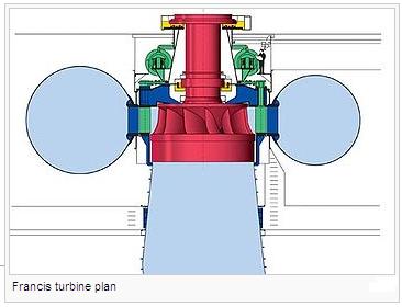
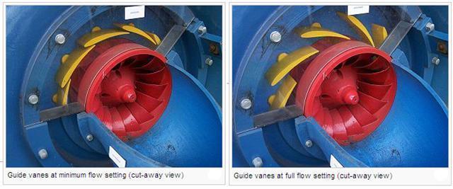
The inlet is a spiral. The water comes to the runner tangentially through guide vanes, which makes the runner to spin. Efficiency of operation can be influenced by adjusting the guide vanes, depending on different water flow conditions. During the movement of the water through the runner, the water spins faster, which is caused by the law of angular momentum conservation. Thus, together with the pressure of the water, the efficiency of the turbine is significantly increased. At the outlet the water is decelerated and its pressure is recovered. Special runner features shaped as a cup cause that the water stops swirling and leaves with very little kinetic energy.
Application
Francis turbines can be used for a very wide head range between 20 and 700 metres, and their output power differs from one kilowatt up to one gigawatt. They are both used for direct electrical production or for pumped storage. In the second case they function as a pump and fill a reservoir, when the power demand is low, to be able to generate power during peak hours.
Vocabulary
invent – vynalézt
invention – vynález
water wheel – vodní kolo
efficient – výkonný
outward – vnější
inward – vnitřní
per cent – procent
propose – navrhnout
radial – radiální
pressure – tlak
transmit – přenést
base – základna
dam – přehrada
inlet – vstup
outlet – výstup
runner – lopatkové kolo
tangentially – tangenciálně
guide vanes – vodící lopatky
spin – otáčet se
adjust – nastavit
water flow – vodní průtok
law of angualr momentum conservation – zákon zachování hybnosti
decelerate – zpomalit
recover – obnovit
swirl – vířit
head – vodní spád
power – výkon
pumped storage – akumulace energie přečerpáním vody do vyšší nádrže
pump – čerpadlo
power demand – poptávka po elektrické energii
generate – vyrábět
peak hours – doba špičky
cut-away – znázorněný na příčném řezu
Obrázky a fotografie použité v této kapitole pochází ze stránek {Wikimedia Commons XH http://commons.wikimedia.org}, kde byly zveřejněny pod licencí {GNU FDL XH http://commons.wikimedia.org/wiki/Commons:GNU_Free_Documentation_License}.
Kapitola 2: Cvičení
- Studenti zpracují na téma Francis Turbine powerpointovou prezentaci.
Kapitola 3: Kontrolní otázky
- Can you briefly describe a Francis turbine?
- How does it operate?
- What is its application?
Kapitola 4: Autotest
- How much are Francis turbines used?
- Francis turbines need
- What does the water entering the turbine go through?
- The vanes
- What is the output power of Francis turbines.
Lekce 3: Kaplan Turbine
Kapitola 1: Kaplan Turbine
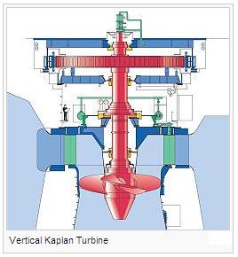
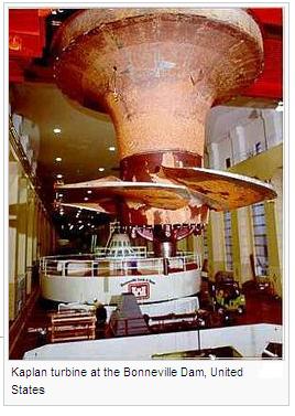
The Kaplan turbine is a type of a water turbine with adjustable blades, invented by an Austrian engineer Viktor Kaplan in 1913. These turbines are used in low-head power production, which is not possible with Francis turbines.
Operation
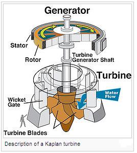
When the fluid flows through the Kaplan turbine, it changes its pressure and gives up its energy. The inlet of the turbine looks like a scroll and wraps around the wicket gate. The water goes through the gate in a spiral and falls onto a propeller, which is forced to spin. The outlet is a draft tube. Here the water decelerates and thus the kinetic energy is recovered.
The draft tube has to be full of water, but it does not have to be at the bottom of the water flow. However, lower location helps to keep the suction on the turbine blades smaller. The suction causes pressure drop, which results in cavitation.
Application
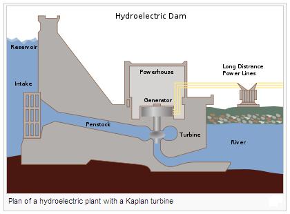
Kaplan turbines have very high efficiency, usually over 90 per cent, although it can be lower in very low-head applications. Production and installation of large turbines of this type is very expensive, but they work reliably for a long time. Usually they are used to produce electric power in the lowest head hydro sites. Microturbines for private usage are also produced and they can be used for power production with 60 centimeters of head.
Vocabulary
turbine – turbína
adjustable blades – nastavitelné lopatky
head – hydraulický spád
power production – výroba energie
electric power – elektrická energie
fluid – tekutina
pressure – tlak
inlet – vstupní otvor
outlet – výstupní otvor
wicket gate – rozváděcí lopatky, rozvaděč
propeller – vrtule
draft tube – sací potrubí
suction – podtlak
cavitation – kavitace
Obrázky a fotografie použité v této kapitole pochází ze stránek {Wikimedia Commons XH http://commons.wikimedia.org}, kde byly zveřejněny pod licencí {GNU FDL XH http://commons.wikimedia.org/wiki/Commons:GNU_Free_Documentation_License}.
Kapitola 2: Cvičení
- Studenti zpracují na téma Kaplan Turbine powerpointovou prezentaci.
Kapitola 3: Kontrolní otázky
- Can you briefly describe a Kaplan turbine?
- How does it operate?
- What is its application?
Kapitola 4: Autotest
- What is the advantage of Kaplan turbines?
- What happens with the speed of the water in the turbine?
- How does the water flow through the gate?
- Where is the draft tube?
- What can the suction on the turbine blades cause?
Lekce 4: Banki Turbine
Kapitola 1: Banki Turbine
Banki turbine, also known as aBanki-Michell turbine, Ossberger turbine or crossflow turbine, is a type of a water turbine developed by Hungarian engineer Donát Bánki in 1917.
Description
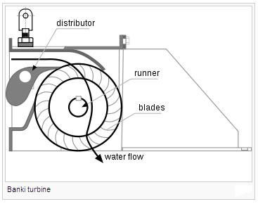
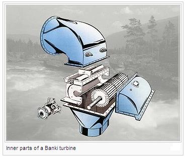
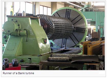
The Banki turbine has a cylindrical runner with a horizontal shaft, which can possess up to 37 blades. The blades are arranged radially and tangentially. They are very sharp, which reduces the water resistance. The turbine has trough-shaped blades, their cross-section is an incomplete circle.
Operation
While most water turbines have axial or radial water flows, in Banki turbine the water goes through transversely, that means across the turbine blades. After it flows into the top of the turbine, it makes the wheel rotating by its weight. When it flows past the blades into the middle of the turbine, its direction is changed, thanks to which more power is gained.
Application
Because the Banki turbine is a combination of the impulse and reaction turbines, it can be used in a wide range of heads. Although their efficiency is lower than the efficiency of other turbines, they are quite popular because of their low prize and easy installations. That is why they are used especially in very small hydropower units with the ouput of less than 2,000 kilowatts and with heads smaller than 200 metres.
Vocabulary
Banki turbine, crossflow turbine – Bánkiho turbína
developed – vyvinutý
cylindrical – válcový
runner – lopatkové kolo
shaft – hřídel
blade – lopatka
radially – radiálně, paprskovitě
radial – radiální
reduce – snížit
resistance – odpor
trough-shaped – ve tvaru žlabu
cross-section – průřez
axial – axiální
transversely – příčně
weight – hmotnost
direction – směr
power – energie
application – využití
head – hydraulický spád
efficiency – účinnost
hydropower unit – blok vodní elektrárny
output – výkon
Obrázky a fotografie použité v této kapitole pochází ze stránek {Wikimedia Commons XH http://commons.wikimedia.org}, kde byly zveřejněny pod licencí {GNU FDL XH http://commons.wikimedia.org/wiki/Commons:GNU_Free_Documentation_License}.
Kapitola 2: Cvičení
- Studenti zpracují na téma Banki Turbine powerpointovou prezentaci.
Kapitola 3: Kontrolní otázky
- Can you briefly describe a Banki turbine?
- How does it operate?
- What is its application?
Kapitola 4: Autotest
- What is the shape of the runner of a Banki turbine?
- What is the position of the shaft?
- Why are the blades very sharp?
- What is the cross-section of the blades?
- How does the water go through Banki turbines?
Lekce 5: Deriaz Turbine
Kapitola 1: Deriaz Turbine
Deriaz turbine is a form of a water turbine. It was named in honour of Paul Deriaz, a hydraulic designer and its inventor. It was the first diagonal turbine, invented in 1956.
Description
Deriaz turbine is a mixed-flow turbine, which means that water enters the unit radially and leaves it axially. It is similar to Kaplan turbine but its runner blades are more inclined, and thus it is more suitable especially for medium heads, ranging between 20 and 100 metres. The blades are adjustable and can be rotated around their axis, which is at right angles to the main shaft.
Advantages
Thanks to its construction, the Deriaz turbine has many other advantages:
- The blades can be completely closed so that the runner turns into a smooth cone. This permits to start-up with minimum load while the unit is immersed in water.
- The blades can be adjusted to work efficiently as a pump as well and thus it is suitable for pumped storage plants
- It works efficiently over a wide range of head and load. Unlike with Francis runner blades, this type allows varied pumping loads
- It distributes the pressure and load across the blade from the casing to the hub equally
- It does not have problems with the development of cavitation, no matter of the height of the head
- It has a lower runaway speed when a sudden loss of load occurs in comparison with Kaplan turbine, which results in significant savings in generator costs.
Application
Turbine selection is often based on its specific speed, which can be found from the formula

where n is rotational speed in revolutions per minute, P is the power in horsepower, and H is the head of water in feet. Deriaz turbines are most suitable for N ranging up to 110.
Vocabulary
inventor – vynálezce
mixed-flow – smíšené proudění
radially – radiálně
axially – axiálně
axis – osa
runner – lopatkové kolo
blades – lopatky
inclined – nakloněný
head – hydraulický spád
adjustable – nastavitelný
adjust – nastavit
right angle – pravý úhel
shaft – hřídel
cone – kužel
immersed – ponořený
load – zatížení
efficiently – účinně
pump – čerpadlo
pumped storage plant – přečerpávací elektrárna
cavitation – kavitace
runaway – ve vysokých otáčkách
savings – úspory
specific speed – měrné otáčky
formula – vzorec
rotational speed – rotační rychlost
revolutions per minute – otáčky za minutu
power – výkon
horsepower – koňská síla
range – rozsah
Kapitola 2: Cvičení
- Studenti zpracují na téma Deriaz Turbine powerpointovou prezentaci.
Kapitola 3: Kontrolní otázky
- Can you briefly describe a Deriaz turbine?
- How does it operate?
- What is its application?
Kapitola 4: Autotest
- How does the water flow through the turbine?
- How does it differ from the Kaplan turbine?
- What is the angle between the axis of the blades and the main shaft?
- The blades
- This turbine